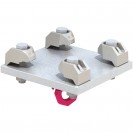
Type ALP Adjustable Lifting Point
Standard rigging and lifting point adjusts to suit the beam width, flange thickness and orientation of the lift. Safely supports loads up to 6,600lbs.
Overview
The Type ALP is an ‘off-the-shelf’ adjustable lifting point, designed to support loads up to 6,600lbs with a +/- 18° lift angle from the supporting steel.
The assembly consists of a large 'Gunnebo' screw on load ring, which can be set in two orientations to suit the lift, and a slotted location plate with Type AAF adjustable girder clamps. Suitable for parallel or tapered beams up to and including 10°, with a flange width range of 23⁄4"; to 173⁄4" and a thickness range of 3⁄16" to 1”. These adjustable features often allow contractors to use just one type of lifting point throughout a project.
Features & Benefits
- Immediately available ‘off-the-shelf’.
- Safe working load up to 6,600lbs.
- Large load ring can be repositioned at 90° to suit the lift orientation.
- Adjusts to fit different sized beams.
- Versatile and easily repositioned.
- Suitable for parallel and tapered beams up to and including 10°.
- Quick to install using standard hand tools.
- Suitable for supporting the lifting and rigging of equipment only.
- The ALP assembly must be regularly inspected for signs of wear or damage, in accordance with the standards / regulations of the country of use.
- Static Safe Working Load values are subject to the capacity of the supporting section. Please refer to the ALP user guide for guidance.
Properties
- Material & Finishes: Type AAF clamps (low temperature SG iron, hot dip galvanized), Location Plate (mild steel or hot dip galvanized) and Load Ring (forged steel, painted).
Technical Specification
| Torque Figures* | Clamping Range | |||||||
|---|---|---|---|---|---|---|---|---|
| Product Code | Load Ring Countersunk Bolts | Type AAF Set Screws | Flange Thickness V | Beam Width U | Safe Working Loads (FOS 5:1) | Max Angle of Load X | ||
| 10.9 Bolt | Torque | 8.8 Bolt | Torque | |||||
| Nm | Nm | mm | mm | |||||
| LALP 3T-1 | M16 | 100 | M12 | 90 | 5 - 26 | 70 - 210 | 3t (29.4kN) | 18° |
| LALP 3T-2 | M16 | 100 | M12 | 90 | 5 - 26 | 190 - 330 | 3t (29.4kN) | 18° |
| LALP 3T-3 | M16 | 100 | M12 | 90 | 5 - 26 | 310 - 450 | 3t (29.4kN) | 18° |
*Torque figures based on bolts / setscrews in an unlubricated condition as supplied.
| Torque Figures* | Clamping Range | |||||||
|---|---|---|---|---|---|---|---|---|
| Product Code | Load Ring Countersunk Bolts | Type AAF Set Screws | Flange Thickness2) V | Beam Width U | Safe Working Loads (FOS 4:1) | Max Angle of Load X | ||
| 10.9 Bolt1) | Torque | 8.8 Bolt1) | Torque | |||||
| ft lb | ft lb | lbs | ||||||
| LALP 3T-1 | M16 (5⁄8") | 74 | M12 (1⁄2") | 66 | 3⁄16" - 1" | 23⁄4" - 81⁄4" | 6600 | 18° |
| LALP 3T-2 | M16 (5⁄8") | 74 | M12 (1⁄2") | 66 | 3⁄16" - 1" | 71⁄2" - 13" | 6600 | 18° |
| LALP 3T-3 | M16 (5⁄8") | 74 | M12 (1⁄2") | 66 | 3⁄16" - 1" | 123⁄16" - 173⁄4" | 6600 | 18° |
1) Metric bolts, nearest imperial / UNC equivalent shown in brackets.
2) Packing pieces can be used to increase the clamping range. Please contact Lindapter Technical Support for more details.
* Torque figures based on fasteners in an unlubricated condition.
How can we
help you?
Reasons to choose Lindapter
-
Save time and money
Clamping two steel sections together avoids time-consuming welding or conventional drilling and bolting.
-
Safer connections
Drilling and welding in the field is avoided, removing the need for hot work permits and encouraging safer site conditions.
-
High strength
Lindapter clamps are manufactured from high strength materials to resist high load requirements and harsh environments.
-
Industry leading approvals
Lindapter has earned a reputation synonymous with safety and reliability, gaining multiple independent approvals.
-
Adjustable
Quickly align steel sections by sliding the section into the correct position before tightening the Girder Clamp to complete the installation.
-
Free connection detailing
Lindapter’s experienced Engineers can detail a custom connection based on your specific requirements free of charge.
You must have a Lindapter account to access this content
Log in to your account
Register for an account
Don't have an account?
Click here to registerAlready registered?
If you have registered for an account but have not received your confirmation email, please click here to resend.

Headquarters
Lindapter InternationalLindsay House, Brackenbeck Road
Bradford, West Yorkshire
BD7 2NF
United Kingdom Map and directions
news
- Environmental Policy
- T&Cs
- Privacy
- Cookies
- © Lindapter International 2026. All rights reserved.


