


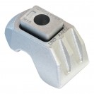
Type CF High Slip Resistance Clamp
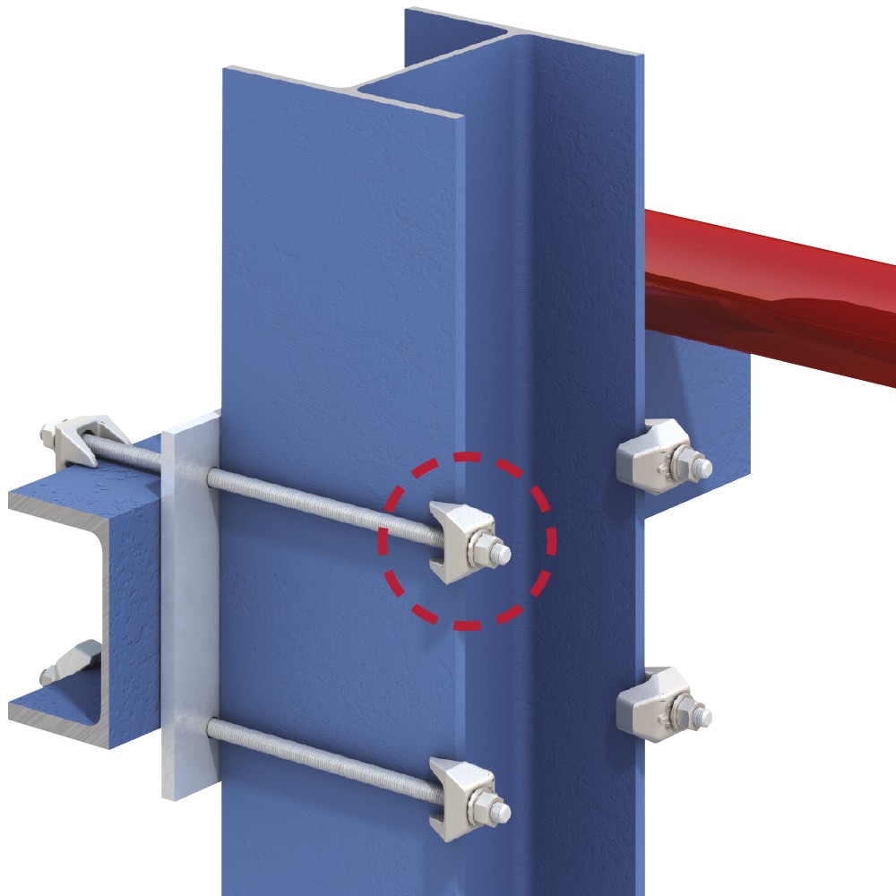
High slip resistance girder clamp designed to hook over the flange of beams, angles and channels to connect opposing steel sections.
Overview
The Type CF girder clamp is used to achieve a fast connection where the flanges of steel beams, angles or channels are opposing each other. The high slip resistance clamp is designed to be used in a two clamp configuration and to hook over the edge of the flange. A bolt, threaded rod or other threaded item is used to connect the two clamps and complete the assembly. Type CF can also be combined with our other HSR girder clamp products to make connections from a flange edge to the flat face of a steel section. Manufactured from SG iron with a hot dip galvanized finish to provide high performance and anti-corrosion protection.
Features & Benefits
- Hooks over flange edge to allow connection of opposing sections.
- High slip resistance for tensile, frictional and combined load applications.
- Suitable for parallel and tapered flanges up to and including 10°.
Approvals
Click on an approval logo to download the certificate or report.


Location & End Plates
Location plates are required when securing two sections together with clamps attached to the upper and lower sections with both clamps directly opposing each other. The plate is positioned between the two sections to hold the bolts at the correct centers and should be fabricated to the dimensions shown in the datasheet.
End Plates should be used when clamps are attached to the supporting section only. The End Plate holds the bolts at the correct centers and should be fabricated to the dimensions shown in the datasheet.
Properties
- Manufactured from SG iron to BS EN 1563.
- Available with hot dip galvanized finish.
- Reaction to fire: A1 (Steel)
Durability and corrosion protection:
| Corrosivity Class | Galvanized Steel |
| C1 | More than 50 years |
| C2 | More than 50 years |
| C3 | More than 20 years |
For C4 and C5 corrosion categories contact us.
Technical Specification


| Safe Working Loads | Dimensions | |||||||||
|---|---|---|---|---|---|---|---|---|---|---|
| Product Code | Bolt 8.8 Z | Tensile / 1 Bolt (FOS 5:1) | Slip1) / 2 Bolts (FOS 2:1) | Tightening Torque* | Clamping Range V | Y | X | T | Width | |
| Painted Steelwork2) | Galvanised Steelwork | |||||||||
| kN | kN | kN | Nm | mm | mm | mm | mm | mm | ||
| LCF050 | M12 | 8.5 | 3.4 | 3.9 | 90 | 6 - 13 | 32 | 14 | 21 - 29 | 46 |
| LCF2050 | M12 | 8.5 | 3.4 | 3.9 | 90 | 12 - 20 | 39 | 16 | 28 - 37 | 48 |
| LCF062 | M16 | 16 | 8 | 10 | 240 | 8 - 16 | 44 | 18 | 25 - 33 | 56 |
| LCF2062 | M16 | 16 | 8 | 10 | 240 | 15 - 25 | 50 | 21 | 35 - 47 | 62 |
| LCF075 | M20 | 26.3 | 13 | 16 | 470 | 10 - 19 | 53 | 22 | 30 - 41 | 65 |
| LCF2075 | M20 | 26.3 | 13 | 16 | 470 | 18 - 30 | 64 | 27 | 41 - 55 | 70 |
| CF combinations with other Lindapter clamps | ||||||||||
| CF + A3) | M12 | 5.8 | 0.9 | 0.9 | 69 | |||||
| CF + A3) | M16 | 8.5 | 1.7 | 1.7 | 147 | |||||
| CF + A3) | M20 | 14.7 | 3.0 | 3.0 | 285 | |||||
| CF + AF / AAF | M12 | 8.5 | 3.4 | 3.9 | 90 | |||||
| CF + AF / AAF | M16 | 16.0 | 8.0 | 10.0 | 240 | |||||
| CF + AF / AAF | M20 | 26.3 | 13.0 | 16.0 | 470 | |||||
1) Slip resistant values calculated against movement exceeding 0.1mm.
2) Shot blast and painted steelwork.
3) Also applies to Type B, Type LR, Type D2 and Type BR.
* Torque figures based on bolts / setscrews in an unlubricated condition.
![]() For Characteristic Resistances when designing a connection to Eurocode 3, please refer to DoP No.011
For Characteristic Resistances when designing a connection to Eurocode 3, please refer to DoP No.011
| Safe Working Loads | Dimensions | |||||||||
|---|---|---|---|---|---|---|---|---|---|---|
| Product Code | Bolt Grd. 5 / A325 Z | Tensile Resistance / 1 Bolt (FOS 5:1) | Slip Resistance1) / 2 Bolts (FOS 2:1) | Tightening Torque* | Clamping Range V | Y | X | T | Width | |
| Painted Steel2) | Galvanized Steel | |||||||||
| lbs | lbs | lbs | ft lb | |||||||
| LCF050 | 1⁄2" | 1911 | 764 | 877 | 66 | 1⁄4" - 1⁄2" | 11⁄4" | 9⁄16" | 13⁄16" - 11⁄8" | 113⁄16" |
| LCF2050 | 1⁄2" | 1911 | 764 | 877 | 66 | 1⁄2" - 3⁄4" | 19⁄16" | 5⁄8" | 11⁄8" - 11⁄2" | 17⁄8" |
| LCF062 | 5⁄8" | 3597 | 1798 | 2248 | 177 | 5⁄16" - 5⁄8" | 13⁄4" | 11⁄16" | 1" - 11⁄4" | 23⁄16" |
| LCF2062 | 5⁄8" | 3597 | 1798 | 2248 | 177 | 5⁄8" - 1" | 2" | 13⁄16" | 13⁄8" - 17⁄8" | 27⁄16" |
| LCF075 | 3⁄4" | 5901 | 2922 | 3597 | 347 | 3⁄8" - 3⁄4" | 21⁄16" | 7⁄8" | 13⁄16" - 19⁄16" | 29⁄16" |
| LCF2075 | 3⁄4" | 5901 | 2922 | 3597 | 347 | 3⁄4" - 13⁄16" | 21⁄2" | 11⁄16" | 15⁄8" - 23⁄16" | 23⁄4" |
| CF combinations with other Lindapter clamps | ||||||||||
| CF + A3) | 1⁄2" | 1304 | 202 | 202 | 50 | |||||
| CF + A3) | 5⁄8" | 1911 | 382 | 382 | 108 | |||||
| CF + A3) | 3⁄4" | 3305 | 674 | 674 | 210 | |||||
| CF + AF / AAF | 1⁄2" | 1911 | 764 | 877 | 66 | |||||
| CF + AF / AAF | 5⁄8" | 3597 | 1798 | 2248 | 177 | |||||
| CF + AF / AAF | 3⁄4" | 5901 | 2922 | 3597 | 347 | |||||
1) Slip resistant values calculated against movement exceeding 0.004" / 0.1mm.
2) Shot blast and painted steel.
3) Also applies to Type B, Type LR and Type BR.
* Torque figures based on fasteners in an unlubricated condition.

How can we
help you?


Reasons to choose Lindapter
-

Save time and money
Clamping two steel sections together avoids time-consuming welding or conventional drilling and bolting.
-

Safer connections
Drilling and welding in the field is avoided, removing the need for hot work permits and encouraging safer site conditions.
-

High strength
Lindapter clamps are manufactured from high strength materials to resist high load requirements and harsh environments.
-

Industry leading approvals
Lindapter has earned a reputation synonymous with safety and reliability, gaining multiple independent approvals.
-

Adjustable
Quickly align steel sections by sliding the section into the correct position before tightening the Girder Clamp to complete the installation.
-

Free connection detailing
Lindapter’s experienced Engineers can detail a custom connection based on your specific requirements free of charge.
You must have a Lindapter account to access this content
Log in to your account
Register for an account
Don't have an account?
Click here to registerAlready registered?
If you have registered for an account but have not received your confirmation email, please click here to resend.
Headquarters
Lindapter InternationalLindsay House, Brackenbeck Road
Bradford, West Yorkshire
BD7 2NF
United Kingdom Map and directions
news
- Environmental Policy
- T&Cs
- Privacy
- Cookies
- © Lindapter International 2024. All rights reserved.