


Type HD Rail Clamp
High strength clamp for low speed rail applications. Provides lateral adjustability for fast and precise rail alignment.
Overview
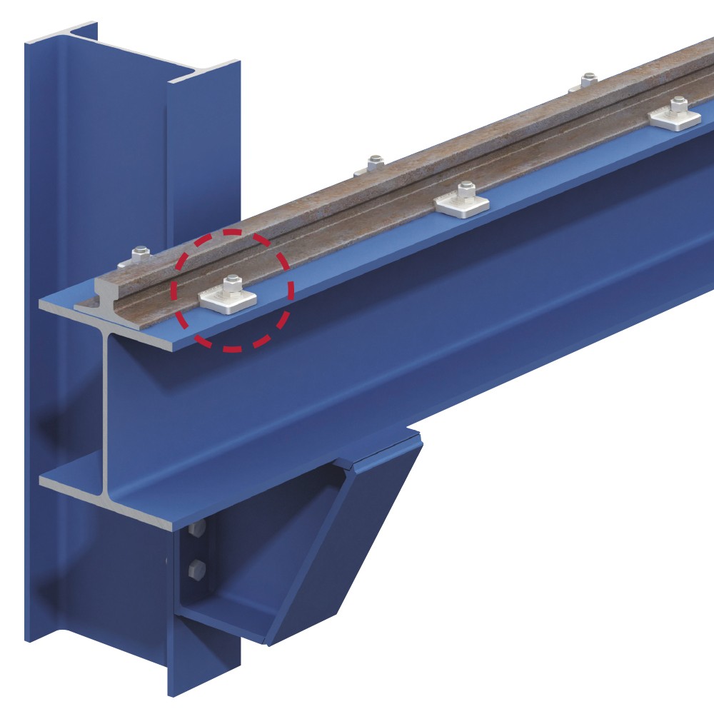
The Type HD is used to secure sections of rail or crane lines in low speed applications, up to 200 feet per minute, such as ground track, elevated rail and overhead gantries. The rail clip features a rotatable central component that provides a high degree of lateral adjustability. It allows contractors to quickly and precisely align rails before securing them in position using standard hand tools. The clamps are manufactured from high strength SG iron, creating a reliable connection that minimizes maintenance requirements.
The clips are used in a variety of environments including train maintenance depots, industrial facilities, water treatment plants, dam/dockside cranes, automated warehouses and power stations. Three product variants are available, each in size 3⁄4"; to meet the diverse requirements of each industry and application (see product options below for more details).
Product Options
Type HD Soft
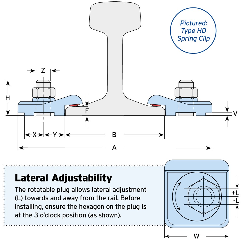
This clip does not touch the top of the rail, which allows the rail to lift slightly to accommodate rail wave, reducing stress and fatigue in the rail and clips.
Type HD Hard
Designed to hold the rail down tightly to prevent rail uplift. Like other Type HD rail clips, it is made from high strength SG iron.
Type HD Spring
An elastomer spring provides vertical restraint while still allowing the rail to lift with rail wave. It also reduces track running noise.
For product comparison chart download datasheet.
Features & Benefits
- High strength clamp.
- Suitable for all rails with tapered flanges and crane speeds up to 200ft/min.
- High degree of lateral adjustability.
- No rail damage as drilling or welding the rails is not required.
- Safely and easily secures rail using only hand tools.
- Three options available for various requirements.
- Overcomes issues with misalignment of studs.
- Contact Lindapter for wheel loads above 89.9 kips or lateral loads higher than wheel loads.
- Please contact Lindapter to ensure suitability of component for application.
Approvals
Click on an approval logo to download the certificate or report.


Properties
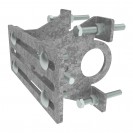
- Manufactured from SG iron to BS EN 1563.
- Available with zinc plated, hot dip galvanized or sheraplex finish if required.
Technical Specification
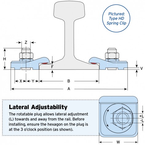
| Normal Lateral Conditions | High Lateral Conditions | Dimensions | Distances1) | Width | |||||||||
|---|---|---|---|---|---|---|---|---|---|---|---|---|---|
| Clip Type | Product Code | Bolt 8.8 | SWL (FOS 4:1) | Tightening Torque* | SWL (FOS 4:1) | Tightening Torque* | Leg Length3) | Stud Length3) | Lateral Adjustment | Plate Width | Y | X | W |
| Z | V | H | L | min. A | |||||||||
| kN | Nm | kN | Nm | mm | mm | mm | mm | mm | mm | mm | |||
| Soft | LHD075S | M20 | 22.5 | 185 | 46.0 | 450 | F - 4 | F + 40 | +/- 11.5 | B + 137 | 30 | 27 | 74 |
| Hard | LHD075H2) | M20 | 22.5 | 185 | 46.0 | 450 | F - 8 | F + 38 | +/- 11.5 | B + 137 | 30 | 27 | 74 |
| Spring | LHD075SP | M20 | 22.5 | 185 | 46.0 | 450 | F - 7 | F + 40 | +/- 11.5 | B + 137 | 30 | 27 | 74 |
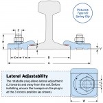
1) Based on plug set at 3 o’clock position.
2) Not suitable for use with a resilient pad.
3) Please specify the required leg length (V) when ordering. If you are using the resilient pad with Soft or Spring types (resilient pads are not suitable with Hard), increase the leg length and stud length (H) by the thickness of the pad.
* Torque figures based on bolts / setscrews in an unlubricated condition.
| Normal Lateral Conditions | High Lateral Conditions | Dimensions | Distances1) | Width | |||||||||
|---|---|---|---|---|---|---|---|---|---|---|---|---|---|
| Clip Type | Product Code | Bolt Grd. 5 Z | SWL (FOS 4:1) | Tightening Torque* | SWL (FOS 4:1) | Tightening Torque* | Leg Length3) V | Stud Length3) H | Lateral Adjustment L | Plate Width min. A | Y | X | W |
| lbs | ft lb | lbs | ft lb | ||||||||||
| Hard | LHD075H2) | 3⁄4" | 5060 | 136 | 10340 | 332 | F - 5⁄16" | F + 11⁄2" | +/- 7⁄16" | B + 53⁄8" | 13⁄16" | 11⁄16" | 215⁄16" |
| Soft | LHD075S | 3⁄4" | 5060 | 136 | 10340 | 332 | F - 3⁄16" | F + 19⁄16" | +/- 7⁄16" | B + 53⁄8" | 13⁄16" | 11⁄16" | 215⁄16" |
| Spring | LHD075SP | 3⁄4" | 5060 | 136 | 10340 | 332 | F - 5⁄16" | F + 19⁄16" | +/- 7⁄16" | B + 53⁄8" | 13⁄16" | 11⁄16" | 215⁄16" |
1) Based on plug set at 3 o’clock position.
2) Not suitable for use with a resilient pad.
3) Please specify the required leg length (V) when ordering. If you are using the resilient pad with Soft or Spring types (resilient pads are not suitable with Hard), increase the leg length and stud length (H) by the thickness of the pad.
* Torque figures based on fasteners in an unlubricated condition.

How can we
help you?


Reasons to choose Lindapter
-

Save time and money
Clamping two steel sections together avoids time-consuming welding or conventional drilling and bolting.
-

Safer connections
Drilling and welding in the field is avoided, removing the need for hot work permits and encouraging safer site conditions.
-

High strength
Lindapter clamps are manufactured from high strength materials to resist high load requirements and harsh environments.
-

Industry leading approvals
Lindapter has earned a reputation synonymous with safety and reliability, gaining multiple independent approvals.
-

Adjustable
Quickly align steel sections by sliding the section into the correct position before tightening the Girder Clamp to complete the installation.
-

Free connection detailing
Lindapter’s experienced Engineers can detail a custom connection based on your specific requirements free of charge.
You must have a Lindapter account to access this content
Log in to your account
Register for an account
Don't have an account?
Click here to registerAlready registered?
If you have registered for an account but have not received your confirmation email, please click here to resend.
Headquarters
Lindapter InternationalLindsay House, Brackenbeck Road
Bradford, West Yorkshire
BD7 2NF
United Kingdom Map and directions
news
- Environmental Policy
- T&Cs
- Privacy
- Cookies
- © Lindapter International 2025. All rights reserved.